


请选择项目
- 产品中心
- 解决方案与应用
Pulsed Modulation
发布者:广域信通讯
1 Introduction
Hittite Microwave’s HMC-T2XXX synthesizer series includes the following models: HMC-T2000, HMC-T2100, HMC-T2220, HMC-T2220B, HMC-T2240, and HMC-T2270. This Application Note describes how to combine HMC-T2XXX synthesizers with an HMC-C019 switch module in order to generate pulse modulation.
The HMC-C019 is a high-isolation switch module, typically providing 65 dB of isolation through 20 GHz with 4 dB of insertion loss. It has a 0.1-dB compression point of about 20 dBm across the frequency band, and can operate with input power levels up to 23 dBm. Control is with a 3.5 to 5.0 V control signal, and the turn-on and turn-off times for the switch are both 8.5 ns. Together these characteristics position the HMC-C019 as an ideal switch to cascade with the HMC-T2XXX synthesizers in order to provide pulse modulation capabilities up to 20 GHz.
2 Set-Up
The method of attaching the HMC-C019 to the HMC-T2XXX synthesizer is shown in Figure 1. First, the RF1 SMA connector (pin 1) should be connected through a male-male barrel or high-quality cable to the output of the HMC-T2XXX. Care should be taken in selection of this interconnect to ensure that proper connector styles are used on both ends and that the frequency performance is sufficient to cover the band of interest.
Since the maximum input level for the HMC-C019 while switching is +23 dBm, and this is significantly below the maximum output power generated by the HMC-T2XXX models, it is recommended to use at least a 7-dB attenuator to prevent accidentally damaging the HMC-C019. For proper operation, DC blocking capacitors are needed on the output of the HMC-C019 if the load DC voltages are not at 0Vdc.
Next the HMC-C019 needs to be connected to a 5V power supply. The supply voltage should be connected to pins 4 and 8, with the ground return provided through pins 2 and 6. The current requirement for the supply varies with switching rate, ranging from a typical 2.8 mA for slow switching to 20 mA at the fastest switching speeds.
Then the switch controls need to be connected to pins 3 and 7 of the HMC-C019 module, with ground return again provided through pins 2 and 6. The control voltages range from 0 to 1.5V at 20 μA typical for the off state and 3.5 to 5 V at 1 mA typical for the on state.
Finally the output of the HMC-C019, the SMA connector at pin 5, can be connected to the device requiring a pulsed RF input. This completes the setup for the cascaded HMC-T2XXX and HMC-C019.

Figure 1
3 Typical Results
We will now present a few examples of the pulse-mode performance of an HMC-T2220 connected with an HMC-C019. Figure 2 shows the detected output power level with a 1-MHz modulation and input signals of 50 MHz, 5 GHz, and 20 GHz.
Both the 50-MHz case and the 5-GHz case show 70 dB of on/off ratio, with a little less loss in the switch at 5 GHz. For 20 GHz, the loss is about the same as the 50-MHz case, but the on/off ratio has dropped to about 55 dB.
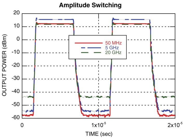
Figure 2
Next, in Figure 3 we see the time-domain response of a 10-MHz modulation signal and a 200-MHz input signal. From this we see that even at a 10-MHz modulation rate, the switching time is sufficient to allow clear distinction between the states. We do note that there is a slight inbalance between the on and off states, so that the duty cycle is only about 40%. This is a result of capacitive loading from the cable and oscilloscope input slowing the rise and fall times of the modulating signal.
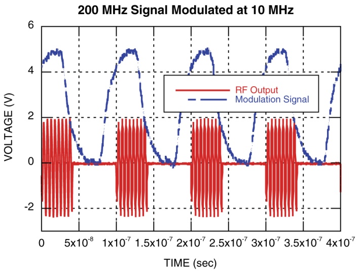
Figure 3
Figure 4 shows the detected output power level for a 10-MHz pulse modulation of a 10-GHz input signal. Note that even with the 110-MHz processing bandwidth of the real-time spectrum analyzer there are only about 15 points per period on these curves. The larger resolution bandwidth and higher internal noise also result in a much higher noise floor for the off state. However, this does confirm our previous measurement that even with a 10-MHz modulation rate we achieve clear distinction between the on and off states.
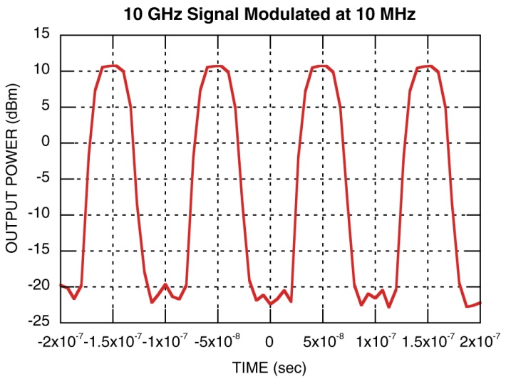
Figure 4
4 Limitations
Note that the HMC-C019 should not be hot-switched above +23 dBm, so care needs to be taken to ensure that the HMC-T2XXX output power is not allowed to exceed that level. For best operation, the output level of the HMC-T2XXX should be set to a maximum value of +20 dBm, which will typically provide +16 dBm of modulated output power.
Also, it should be noted that the operating bandwidth of the HMC-C019 is 20 GHz, so this solution would not be appropriate for modulation of carrier frequencies beyond 20 GHz.
5 Conclusions
We have demonstrated how the HMC-C019 switch can be cascaded with HMC-T2XXX synthesizers in order to provide pulse modulation capabilities up to 20 GHz.
This cascade supports pulse modulation rates over 20 Mbps, with typical output power levels up to +16 dBm.